Download Sort:
OMRON
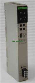
OMRON CVM1-CPU11-V2 Ladder Diagrams Manual CVM1-CPU11-V2 Macro Reference
Product model: CVM1-CPU11-V2
Name: Safety Light Curtain
Brand: OMRON
Sort: Ladder Diagrams Macro Reference
File language: English
Download link: OMRON CVM1-CPU11-V2 Macro Reference
C500-OC I/O Unit Transistor Output 16 pts C500-OC223-E(3G2A5-OC223-E).
AC250/DC24V 2A.Specification: Platinum resistance thermometer input (Pt, JPt),
ON/OFF or advanced PID control,
tran-sistor (PNP) output, 2 loops.Power supply: DC power supply.
Output method: Transistor output sink type.
Inputs points: 24 points CVM1-CPU11-V2 Macro Reference.
Outputs points: 16 points.Name: PC Link Module CVM1-CPU11-V2
Model: C200H-LK401.
Communications method: 2-conductor, half duplex.
PC Link Unit
Distributed control using the PC Link Unit.Name: Controller Link Module.
Model: C200HW-CLK21.
Communications method: N: N token bus.
Code Manchester: codePower supply: AC power supply.
Output method: Transistor output sink type.
Inputs points: 12 points CVM1-CPU11-V2 Macro Reference.
Outputs points: 8 points.Model: CPM2C-20C1DTM-D. CPU Unit: Units with 20 I/O points.
2 MIL connectors.
Inputs: 12 inputs.
Outputs: 8 outputs.
Input type: 24 VDC.
Output type: sinking transistor.
Internal clock: Yes.UM: 15.2K words.
DM: 6K words.
EM: 6K words.
Instruction processing time (basic instructions): 0.15 µ.s min.
No. of I/O points: 880 points.
Max. no.of con-necting Expansion I/O Racks: 2 Racks CVM1-CPU11-V2 Macro Reference.
Max. no. of connecting High-density I/O Units(i.e., Group-2): Unavailable.
Max. no. of con-necting Special I/O Units: 10.
RS-232C: NO.General Information
The C200HS-SLK12 SYSMAC LINK fiber-optic module connects the PLC to the SYSMAC
LINK fiber-optic token bus peer-to-peer communications network. An external power supply option provides direct pass-through communications in case of modulName: Three-tier Screw Terminal Block.
Specifications: Inputs/Outputs;
8 inputs/8 outputs; NPN;
With Short-circuit and,
Disconnected Line Detection.
"Easy" and "Flexible" system expansion,
with linked CC-Link and CompoNet.
Branching is easily made with CompoNet.
Wiring material cost can be reduced.
Bitt-level I/O distribution reduces,
wiring in the system CVM1-CPU11-V2 Ladder Diagrams Manual.
A wide variety of CompoNet Slave Units,
contribute to system size reduction.
Seven-segment Display on the Gateway Unit,
helps to detect errors on site. CVM1-CPU11-V2 Ladder Diagrams Manual.
The Participation Flags and Communications,
Error Flags can be checked at the Host,
Controller to detect the location and,
content of the error. v
Related products
OMRON
Communication Link
CVM1-CLK21

CVM1-CL Special I/O Unit Communication L
OMRON
CPU
CVM1-CPU21-V2

Model : CVM1-CPU21-V2.
Ladder only 2, 0
OMRON
CPU
CVM1-CPU11-V2

I/O capacity: 1, 024 pts 4, 096 max. wi
OMRON
Controller Link
CVM1-CLK52

CVM1-CL Accessory MODULE, CONTROLLER LIN
